



News
Frac Hose Selection Guide: Data Needed for a High-Pressure Hose Assembly
A nominal bore and a pressure number are not enough to specify a high-pressure fracturing hose assembly. Before comparing products, document where the line will be installed, what fluids it will carry, the operating pressure and temperature range, the required flow and routing, and the exact connections at both ends. Those inputs allow an engineering team to review the complete assembly rather than infer its suitability from the hose body alone.
This frac hose selection guide is for equipment integrators, oilfield service teams, and technical buyers preparing a specification or internal purchase request. Use it to separate confirmed requirements from open questions before reviewing available configurations. It is a planning guide, not an installation procedure or approval for a particular pressure system.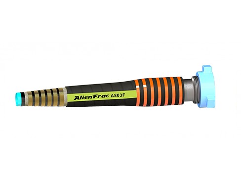
Frac Hose Selection Starts With the Complete Operating Condition
Why hose selection should not begin with diameter alone
Start with the service position. Identify the equipment at each end, the section of the system the assembly will occupy, and its intended duty. A line carrying treatment fluid from a pump to a manifold may have different requirements from a line used for discharge service. Record whether the assembly is for a new layout, an approved replacement, or a change to an existing system. If the duty or route has changed, note the differences rather than treating the old assembly as the specification.
The difference between a hose body and a complete hose assembly
The hose body is the flexible part of the line. The finished assembly includes the hose body, end fittings, and the method used to attach those fittings. The engineering review also needs to account for seals and any adapters at the equipment interfaces. Two assemblies with the same nominal bore and hose construction can have different installed lengths, connection details, or allowable operating conditions.
Use the acid frac hose configurations page to see how product options are grouped. Keep the project data sheet separate: it defines the duty the proposed assembly must meet, regardless of which product is eventually reviewed.
Define the Fluid Media and Service Environment First
Water-based, oil-based, acid-based, and foam fracturing fluids
List the fluids expected to pass through the line during the full service sequence, not only the main treatment stage. Include flushes, cleaning fluids, and any other media that will contact the assembly. For each fluid, record its name or formulation reference, the expected concentration range, the temperature at which it will be conveyed, and whether exposure is continuous or intermittent. Attach the relevant fluid data sheet or an approved formulation reference where available.
Dilute acids, chemicals, and abrasive slurry considerations
Do not leave “dilute acid” or “abrasive slurry” as the final description. For an acid service review, identify the acid and its expected concentration range. For a slurry, identify the solids and supply available information on particle size and loading. If the treatment program changes from one job to another, identify the range the assembly is expected to cover rather than listing only one representative job.
Chemical compatibility and abrasion are separate questions. A lining that is compatible with a fluid is not necessarily suitable for every solids load or duty. Likewise, an abrasion-resistant outer cover addresses external wear; it does not establish how the bore or wetted fittings will perform in an abrasive slurry. Record both the fluid-side and external exposure so they can be reviewed independently.
Temperature, contamination, and chemical-compatibility information
Specify fluid temperature and ambient temperature separately. Note any hot flush, cold start, storage exposure, or external contact with fluids that the assembly is expected to encounter. Review the lining, fittings, seals, and other relevant materials against those conditions. If the fluid formulation is not settled, mark compatibility as pending rather than assuming that the general application description covers the final fluid.
Match Pressure Requirements to the Full Fracturing System
Working pressure versus test pressure
Record the normal operating pressure, the maximum expected system pressure at the proposed location, and any known transient peaks, such as short pressure increases during changes in operating conditions. Use consistent units and identify the engineering document or operating data behind each value. If a number is listed only as “maximum pressure,” confirm whether it refers to an operating limit, a transient, or a test requirement.
Working pressure is the allowable pressure for service under the stated conditions. Test pressure belongs to a defined verification procedure; it is not an allowable operating pressure. If the project specifies a test, record the governing document, the required record, and any inspection or witnessing requirements separately. Do not derive a working-pressure rating or an operating margin from a test-pressure or burst-pressure figure.
Why connected equipment and fittings must be reviewed together
Evaluate the documented rating of the finished assembly, not just the pressure rating printed on the hose. The lowest-rated applicable component can limit the assembly, and the approved assembly configuration or service conditions may impose a lower limit. Separately, verify the connected equipment interfaces, including any valves, adapters, unions, or flanges that form part of the pressure boundary. A higher-rated hose body does not raise the rating of a lower-rated component.
Project procedures, safety margins, and engineering approval
Identify who owns pressure-system approval and which project documents govern the decision. Ask engineering to resolve any uncertainty about pressure peaks, service limits, or the margin required under project rules. Keep relevant operating limits, test requirements, and acceptance criteria in separate fields so that a reviewer can trace each one to its source.
For background on how Qingflex groups its oilfield hose applications, see API 7K and API 16C oilfield hose applications. A reference to either standard does not establish that it applies to every hose or that a specific finished assembly is certified. Confirm the applicable standard, scope, product configuration, and documentation required by the project.
Select the Required Hose Size and Assembly Length
Inside diameter and flow-path considerations
Give engineering the required flow rate or operating flow range, the expected fluid characteristics, and any allowable pressure drop already defined for the line. Record the proposed hose inside diameter separately from the nominal end connection size. A connection can match the equipment mechanically while introducing a restriction that still needs to be reviewed. Where flow or pressure loss is important, include any known restrictions through fittings, adapters, and changes in direction.
If the bore has already been specified in an approved design, cite the drawing revision or line reference. If it has not been sized, record the required flow and mark the bore as subject to engineering review. This is more useful than treating the port size as the hose size, especially when comparing a replacement route with an assembly that has different ends or a different overall length.
Overall assembly length versus hose cut length
Hose cut length is the length of the hose body before the ends are assembled. Overall assembly length is a finished dimension measured between agreed reference points on the end fittings. Face-to-face may be appropriate for some flanged assemblies; other ends can require a different measurement convention. Show the endpoints and tolerance on a drawing rather than relying on a dimension labelled only “length.”
The straight-line distance between two ports is a layout input, not necessarily the finished assembly length. A route around equipment, the fitting geometry, the bend allowance, and any required straight section near an end can change the length needed. For a replacement, provide the existing assembly drawing or identifier if available, and verify that the route and equipment interfaces have not changed.
Routing, bend allowance, movement, and installation clearance
Provide a sketch showing port locations, elevations, obstacles, clearances, and equipment positions that affect the route. Identify whether the assembly remains stationary in service or must accommodate movement that the design team has defined. Check the proposed route against the selected assembly’s published bend limits and installation requirements, including any restrictions near the fittings. Do not use extra hose length as a substitute for reviewing a bend, twist, or contact point.
Choose End Connections and Assembly Configuration
Crimped and built-in construction considerations
Crimped and built-in describe different assembly constructions. Neither term, on its own, establishes pressure capability, fluid compatibility, or interchangeability. Where a project specifies one construction, record whether the requirement comes from an approved drawing, a replacement specification, an equipment interface, or an engineering decision. If the construction is open, compare the crimped and built-in acid fracturing hose options against the same confirmed service data.
Fittings, flanges, hammer unions, and connection standards
Specify End A and End B separately. For each, identify the equipment it mates with, the connection family, nominal size, rating or class where applicable, and the relevant drawing or standard. A threaded connection may require thread form and pitch; a flange may require facing and bolt pattern; a hammer union may require the exact figure and mating-half details. A photograph can help identify a legacy interface, but it does not replace verified connection data.
Include existing adapters in the interface description. If a proposed hose fits only after adding or changing an adapter, treat that as a configuration change for engineering review. It can affect the assembled length, clearance, bore, sealing arrangement, and pressure rating.
Fitting orientation and assembly drawings
Where an assembly has angled connections, specify the relative orientation of the ends on a drawing. Include the viewing direction and reference orientation so both parties interpret the angle the same way. An assembly can have the correct bore, overall length, and fittings and still be unsuitable if the ends cannot align without twisting the hose. Flag uncertain dimensions or orientations before the assembly drawing is approved.
Evaluate Abrasion Exposure and External Protection Needs
Ground contact, dragging, and repeated handling
Separate handling exposure from operating exposure. A hose may be clear of the ground when connected but still encounter rough surfaces during transport, staging, or repeated rig-up and removal. Record where contact occurs, which part of the assembly is affected, and whether an alternative route or handling arrangement can avoid it. If external protection is required, identify its intended location and any limits on clearance or inspection access.
Movement near pumping equipment and manifolds
Mark contact risks near brackets, frames, manifold transitions, adjacent lines, and vehicle routes. Check the locations at each expected equipment position, not only in the layout shown on an initial drawing. If a replacement repeatedly shows wear at the same point, submit that location and the service history with the layout. It gives engineering a reason to review the route instead of assuming a different cover will resolve the problem.
Why cover damage should be considered during project planning
Plan how the cover and fitting transitions will remain accessible for inspection. A protective sleeve or guard may address a particular exposure, but it should be reviewed for compatibility with the assembly and the site inspection procedure. Record known wear points and any protection requirements on the layout. The project’s inspection criteria should determine how damage is assessed; this selection checklist does not establish acceptance or retirement limits.
Prepare Documentation and Verification Requirements
Product drawings and dimensional confirmation
Identify which drawings are needed for engineering review and which must be approved before manufacture. A useful assembly drawing shows the bore, finished length and measurement points, length tolerance, both end connections, and any orientation requirement. Link the drawing to its revision and the relevant equipment interface so that the technical review and purchase request describe the same assembly.
Pressure-related records and inspection requirements
Specify the evidence the project needs: for example, an assembly rating document, a pressure-test record if required, an inspection report, or traceability documentation. Distinguish between information needed to approve the proposed design and records required at delivery. If a test record must identify each assembly, state that requirement and how the record should reference the assembly marking. Do not assume that a general product data sheet satisfies an order-specific inspection requirement.
Traceability, marking, packaging, and export requirements
Record the customer part number, tag format, and any serial or batch traceability requirements. State whether documentation must match the marking on each assembly or only identify the shipment batch. Include packing constraints that affect the assembly, such as fitting protection, packaging dimensions, or handling restrictions. If a sample is requested, define whether it is for dimensional fit, marking review, packing approval, or another agreed purpose. A dimensional sample alone does not verify suitability for pressure service.
A Practical Frac Hose Selection Checklist for Procurement Teams
Use the table below as a shared data sheet for field operations, engineering, and procurement. For every open item, record who will confirm it and which drawing, operating record, or project specification will close it. Mark missing values as “to be confirmed”; do not substitute a catalog default for a project requirement.
| Information to Collect | What to Record | Suggested Source or Owner |
|---|---|---|
| Application / service position | Line duty, upstream and downstream equipment, and whether this is a new build or replacement | Operations team or system layout |
| Fluid media and concentration | Fluid names, concentration ranges, flush media, and relevant solids information | Treatment program or fluid data sheet |
| Operating temperature | Fluid and ambient ranges, including relevant abnormal or intermittent conditions | Process data or operating history |
| Required working pressure | Normal operating pressure, maximum system pressure at the service position, and known transients | Pressure-system engineer |
| Test or inspection information | Applicable procedure, required records, acceptance criteria, and witness requirements, if any | Project specification or quality team |
| Required inside diameter | Approved bore or flow requirement, pressure-drop limit if specified, and restrictions to review | Flow calculation or engineering drawing |
| Overall assembly length | Finished dimension, measurement endpoints, tolerance, and route drawing | Assembly drawing or field survey |
| End connection type | End A and End B details, mating parts, seals, and any adapters | Equipment drawings or verified interface records |
| Fitting orientation | Relative angle, viewing direction, and reference orientation, where applicable | Dimensioned assembly drawing |
| Routing and abrasion exposure | Movement, bend and clearance constraints, contact points, and protection requirements | Site layout or field assessment |
| Quantity and spares | Installed quantity and separately identified spare assemblies | Equipment list or maintenance plan |
| Product marking | Part number, tag format, and required serial or batch traceability | Asset management or quality team |
| Packaging and export requirements | End protection, shipment marks, package limits, and handling constraints | Logistics or receiving team |
| Drawing or sample requirement | Approval drawing, revision control, and the purpose of any sample | Engineering and quality teams |
Required technical data
For initial screening, prioritize service position, fluid and temperature, maximum pressure, bore or flow requirement, routing dimensions, and both equipment interfaces. Those fields answer a more useful question than “Which model is closest?”: “Is there enough confirmed information to evaluate an assembly for this duty?” If one of those inputs is missing, keep any preliminary comparison provisional.
Required commercial and logistics data
Keep quantities, spares, marking, packing, and document delivery requirements alongside the technical data, but do not use them to resolve engineering questions. For example, spare counts are meaningful only once the team knows which assemblies are interchangeable. Two lines with the same bore may still need separate spares if their end connections, orientation, or installed length differ.
Information that may require engineering review
Flag unknown pressure peaks, an unverified fluid concentration, a changed equipment interface, a tighter route, an added adapter, or an assembly that must accommodate movement. Escalate conflicts explicitly. If a field measurement and an existing drawing give different lengths, record both and ask engineering which one controls rather than averaging them or copying the older value.
Selection Workflow: From Service Data to Model Review
Define Application → Confirm Fluid Media → Verify Pressure System → Determine Size and Length → Select End Connections → Review Abrasion Exposure → Confirm Documentation → Match Product Model: Review Available Acid Frac Hose Models
If an input remains unresolved, assign it to the appropriate owner before final selection. For example, changing an end fitting may affect assembly length or create a bore restriction. When one input changes, recheck the related requirements rather than assuming the previous review still applies.
FAQ About Frac Hose Selection
What is the minimum information needed for initial hose selection?
Start with the service position, fluid and concentration, operating temperature, expected maximum pressure, required bore or flow, routing or length information, and the mating connections at both ends. If a field is unknown, identify it as an open item. Initial screening can narrow the options, but it does not approve an assembly for service.
How should a buyer specify the required hose length?
State the overall finished assembly length, the measurement points at each end, and the dimensional tolerance. If only the port spacing is known, provide the route and connection geometry for review. Do not label port-to-port spacing as the finished assembly length unless the approved drawing defines it that way.
Why do end-fitting details matter if the nominal sizes match?
Nominal size does not confirm that two ends will mate, seal, or meet the required rating. Verify the connection type and identifying details at each end, along with the sealing arrangement and any adapters. If an interface cannot be positively identified from documentation, flag it for verification before selection.
When is a custom fitting arrangement or drawing necessary?
A dimensioned drawing is especially useful when the ends differ, angled fittings need a defined orientation, the interfaces are difficult to identify, or the installation has tight clearances. A custom arrangement should be reviewed whenever a standard assembly cannot match the approved interfaces and route without adding another component or changing the layout.
What documents should be requested before purchase?
Request the information needed to approve the configuration: the proposed assembly drawing, its documented rating and service limits, and confirmation of any project-specific requirements. Identify separately which test records, inspection documents, and traceability records must accompany delivery. The exact package depends on the project specification.
Which changes should trigger another engineering review?
Examples include a new treatment fluid, higher expected pressure, a change in temperature, a different fitting or adapter, a tighter bend, or a new contact point. For replacements, compare the new duty and layout with the approved configuration rather than assuming that matching the old part number resolves every change.
Related Reading for Fracturing Line Planning
If the project has not yet decided which sections should be flexible and which should remain rigid, read frac hose vs steel pipe for fracturing systems. That comparison addresses where each line type may fit; the checklist above defines the inputs needed once a flexible assembly is being evaluated.